In packet radio you have a bunch of different encoding mechanisms. The most common one to get started with is AFSK, audio frequency shift keying. The idea of AFSK is that you encode data into tones, think dial up, and run that into the microphone of your radio. Your radio then takes those tones and transmits them in some form of modulation(think FM, frequency modulation). Someone can then receive your transmission and decode those tones into the data you sent.
The second common form is FSK, frequency shift keying. Unlike AFSK, in FSK you skip the whole audio encoding and directly map data into frequency shifts in FM(frequency modulation). This means that if you are transmitting at 145MHz and you are using a channel spacing of 200KHz, your 1(mark) will be at 145.1Mhz and your zero(space) will be at 144.9MHz.
I recently got a bunch of AX5043 development board to do some FSK experimentation, but I opted for not buying the full kit. I just purchased standalone ADD5043-169-2-GEVK boards to hook to an Arduino. Boy was that a decision that would cost a lot of time and brain power. I mucked around with the AX5043_mbed_Demo on github to get it working on an Arduino and used the notblackmagic.com AX5043 write-up as a reference for some of my register settings. And great, it seemed to be working, but I couldn’t be sure without implementing the RX stack.
So I though, “how hard would it be to setup an SDR to decode the FSK data?” Much harder than you think Ian, much harder.
In this post I’m going to go over how I took raw FSK data and converted it into bits for processing. Later I will implement a basic HDLC/AX.25 packet decoder.
The source code for this demo can be found here: https://github.com/iangoegebuer/python-fsk-decoder
Getting on with it, let’s get some FSK
This will reasonably take 3 steps(4, but we’ll cheat and merge 1&2 together)
- Record the data
- Demodulate the data
- Bit hunting
- Decoding
Step 1&2: Record and demodulate the data
For this step you can do what Tomasz Watorowski does in his page titled “Decoding FSK transmission recorded by RTL-SDR dongle”, and honestly, that’s how I started this. But then I realized SDR# allows you to also tune to and record audio data. With that you can actually skip over the tuning and demodulating steps of his example. Don’t believe me? Here’s the demodulated IQ vs raw audio.
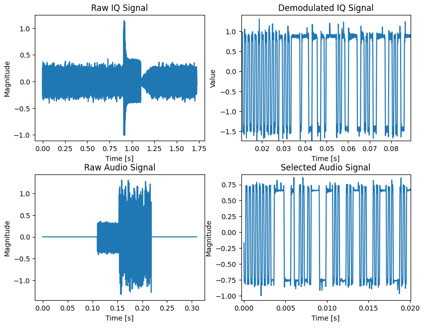
Why is this useful? Well it let’s you eyeball the tuning and offload the demodulation. The demodulation seems to take the most computational time in the original example. If you’re trying to decode incoming FSK data in Python it definitely makes sense to let the SDR software do the work for you.
Make sure to turn off audio filtering in SDR# or else you won’t get useable data.
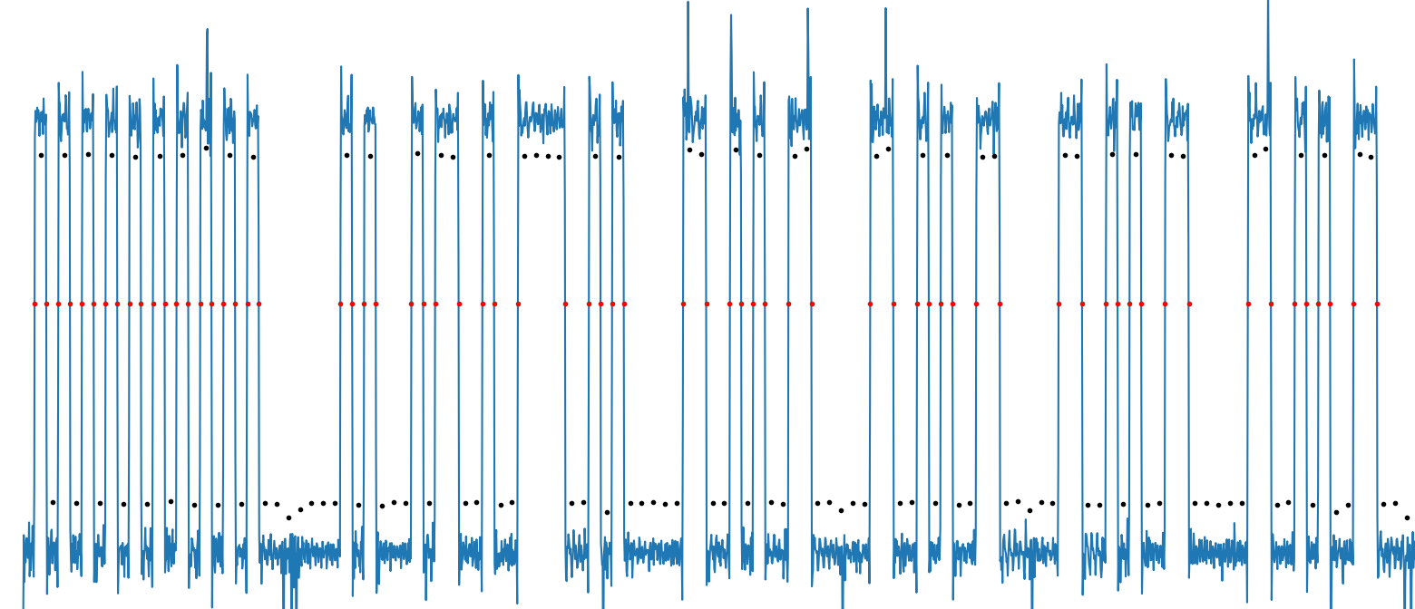
Here’s my reimplementation of some of Tomazs’ work. If you notice the noise once the transmission finishes is much “louder” than the data. Let’s use that to find the end of the data
# Thanks to Tomasz for a lot of inspiration
# https://mightydevices.com/index.php/2019/08/decoding-fsk-transmission-recorded-by-rtl-sdr-dongle/
audio_mag = np.abs(rf)
# mag threshold level
data_start_threshold = 0.02

# indices with magnitude higher than threshold
audio_indices = np.nonzero(audio_mag > data_start_threshold)[0]
# limit the signal
audio = rf[np.min(audio_indices) : np.max(audio_indices)]

audio_mag = np.abs(audio)
# Again, use the max of the first quarter of data to find the end (noise)
data_end_threshold = np.max(audio_mag[:round(len(audio_mag)/4)])*1.05

audio_indices = np.nonzero(audio_mag > data_end_threshold)[0]
# Use the data not found above and normalize to the max found
audio = audio[ : np.min(audio_indices)] / (data_end_threshold/1.05)
Step 3: Bit hunting
Alright so now it’s time to find the actual bits. Tomasz again does a great job with this. His implementation starts to have a hard time if your transmitter sends too many 1s or 0s in a row. But that’s expected. That’s why HDLC(high level data link) is a standard. It exists to make sure that we don’t lose bits.
But I was interested in finding a different way to extract the bits from the data. We can actually infer the data rate by the start “ring” of the message. Before the data is transmitted the transmitter sends a repeating frequency switch. We can use the first few of these and when they cross the zero point to figure out bit rate. We can then use that bitrate to sample the data into 1s and 0s. So let’s first identify the zero crossings and try to figure out the bit rate
zero_cross = []
for i in range(len(audio)):
    if audio[i -1] < 0 and audio[i] > 0:
        zero_cross += [(i, (audio[i -1]+audio[i])/2)]
    if audio[i -1] > 0 and audio[i] < 0:
        zero_cross += [(i, (audio[i -1]+audio[i])/2)]

# Get the first 10 zero crossings, ignoring the first as it may be offset
first_ten = zero_cross[1:11]

samples_per_bit = first_ten[-1][0] - first_ten[0][0]
samples_per_bit = samples_per_bit/(len(first_ten)-1)
samples_per_bit_raw = samples_per_bit

# We will be using this to index arrays, so lets floor to the nearest integer
samples_per_bit = math.floor(samples_per_bit)
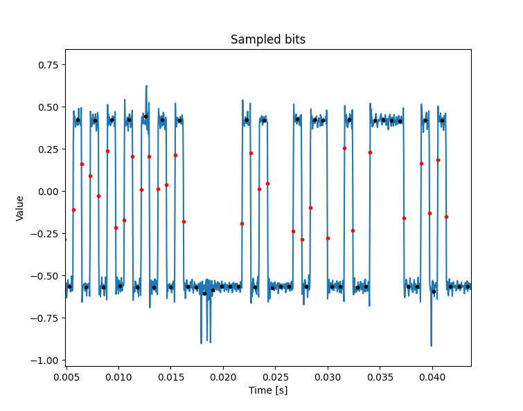
Okay let’s use our new found bit rate and use that to sample. Let’s split up the data on each zero crossing. Then split that up by bits within the high/low blocks.
sampled_bits = []
bits = []
# Let's iterate over the chunks of data between zero crossings
for i in range(len(zero_cross))[:-1]:
    # Now let's iterate over the bits within the zero crossings
    # Note, let's add an extra 1/8th of a sample just in case
    for j in range(math.floor((zero_cross[i+1][0]-zero_cross[i][0] + samples_per_bit/8 )/samples_per_bit)):
        # Let's offset by 1 sample in case we catch the rising and falling edge
        start = zero_cross[i][0]+j*samples_per_bit+1
        end =   zero_cross[i][0]+j*samples_per_bit+samples_per_bit-1
        sampled_bits += [(zero_cross[i][0]+j*samples_per_bit+samples_per_bit/2, np.average(audio[start:end]))]
        bits += [np.average(audio[start:end]) >= zero_cutoff *1]

# Let's convert the true/false data into uint8s for later use
bits = (np.array(bits)).astype(np.uint8)
And with that we have found our bits!
Step 4: Decoding
Now here’s where the real meat of the work I was trying to do comes in. We have demodulated the data and converted it to a series of bits. How do we get from raw data to the original transmitted data? The answer is, it depends of course. How are we encoding it? For our purposes we’re using differential encoding and later we will also be using HDLC.
If it’s just basic differential encoding, that’s easy enough to handle. For every bit, look at the current bit and the last bit. If they are the same you have a one, if they differ you have a zero. Great! Now here’s the weird part. Bytes come in byte order but bits come in least significant bit(LSB) first and shift right.
Below is an example of the data as it comes in. You can see at the 3rd and 4th byte that the actual data is a rotate version of the received data
         0111 1110 | 0100 0101 | 1001 0011 | 1100 1010 | 0000 1100
         0111 1110 | 0001 1000 | 1010 0101 | 1101 0000 | 1111 0101
Received      0x7E |      0x18 |      0xA5 |      0xD0 |      0xF5
Rotated       0x7E |      0x18 |      0xA5 |      0x0B |      0xAF
So a helpful thing about HDLC messages is that they always start with the byte 0x7E. While we won’t fully implement HDLC decoding, we will use that to receive the incoming data and know when the “ring” stops and our data starts.
# https://pysdr.org/content/rds.html#differential-decoding
bits = (bits[1:] - bits[0:-1]) % 2
bits = bits.astype(np.uint8)

current_data = 0
start_data_offset = 0
data = []
found_start = False
for b in range(len(bits)):
    bit = bits[b]
    # Each byte is sent in order but the bits are sent reverse order
    current_data = current_data >> 1
    current_data += (bit*0x80)
    current_data &= 0xff

    # We've already found the start flag, time to store each byte
    if found_start:
        if ((b - start_data_offset) % 8) == 0:
            data.append(current_data)
            current_data = 0
        continue

    # Have we found the flag? 0x7E
    if(current_data == 0b01111110) and b > 4 and not found_start:
        found_start = True
        start_data_offset = b
        data.append(0x7e)
        current_data = 0
    if(current_data == 0b10000001) and b > 4 and not found_start:
        found_start = True
        start_data_offset = b
        data.append(0x7e)
        # Invert the bit value since we found an inverted flag
        bits = (np.array([x for x in bits]) < 1 ).astype(np.uint8)
        current_data = 0
With this we have decoded the received data. In the coming months I will implement an HDLC decoder for the received data. I’ll also go into how I set up SDR# to record the data to process.
To play with it yourself please check out: https://github.com/iangoegebuer/python-fsk-decoder
Permalink
Wow! Good job!
While I am not familiar with the programming language used in your article, I follow the logic about how you got to where you wanted to go in the decoding process. I have been playing and enjoying with my SDR, too.
I admit that I am curious if you have any final application in mind using this process (or perhaps you are just enjoying the journey?!).
Best.
Permalink
Hi,
When I run Decode.py on your provided wav file, I get the following:
python Decode-aq.py -i data-aq.wav
[[-0. -0.]
[-0. -0.]
[-0. -0.]
…
[-0. -0.]
[-0. -0.]
[-0. -0.]]
42496
Traceback (most recent call last):
File “Decode-aq.py”, line 106, in
if audio[i -1] 0:
ValueError: The truth value of an array with more than one element is ambiguous. Use a.any() or a.all()
I managed to find a solution, but end up with “divide by zero” errors, so thought I’d ask.
What version of python are you using to run this??
Thanks in advance.
Permalink
Hello! I am incredibly sorry for the almost 4 year delay in replying.
TBH, I was lucky to find your comment while scrubbing through 2500 bot/spam comments!
If you are still interested. Please open and issue here and we can investigate! https://github.com/iangoegebuer/python-fsk-decoder/issues
Thanks,
Ian